
Guide 1 · overlay
Overlay a drawing on the aerial
Open this example in Plotlay → The same project, ready to explore. Nothing to install.
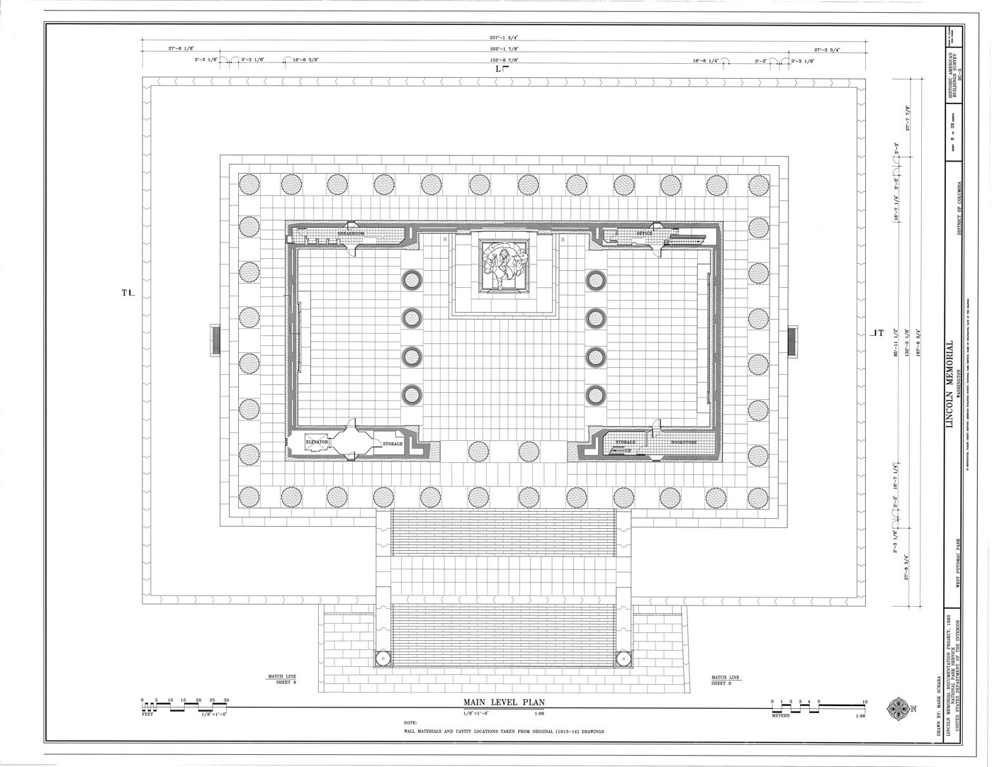
Take a scanned plan, pin it to aerial imagery and check it is right, using a real drawing: the main level plan of the Lincoln Memorial from the Historic American Buildings Survey (public domain), on the District of Columbia's 2023 orthophoto at 8 cm a pixel.
What you need
- The drawing: a PDF, image or DXF. Here, HABS DC-3 sheet 8, Main level plan, a 3840 px scan.
- An aerial where you can see the same corners. In Washington DC, choose Map → Washington DC aerial 2023 (8 cm); in the US generally, US aerial (USDA NAIP); in NSW, NSW aerial imagery.
Steps
- Open the site. New map project → type
Lincoln Memorialor paste a Google Maps link. Switch the base map to the DC aerial. - Add the drawing. Add overlay → Floor plan, drawing or photo and choose the file. It drops in the middle of the view, unplaced.
- Work out the orientation first. On this sheet the steps (which face east, toward the Reflecting Pool) are at the bottom, so the drawing is rotated: its top-left corner is the terrace's south-west corner. Plotlay solves the rotation; you only need to click matching corners.
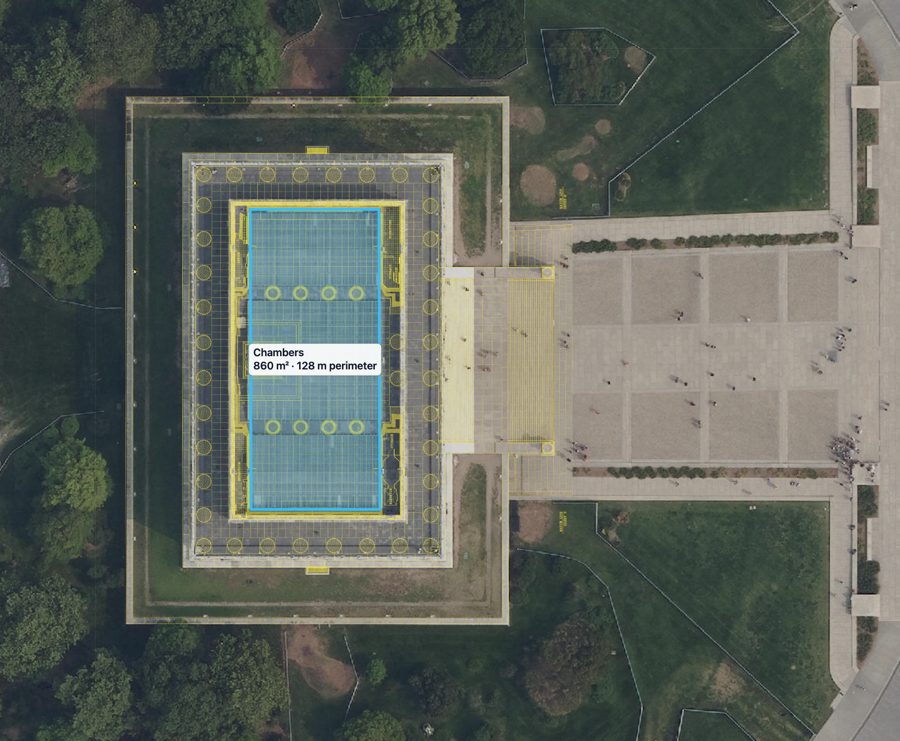
- Pin four corners. Pin to map… opens the drawing and the aerial side by side. Click the outer corner of the terrace on the drawing, then the same corner on the aerial. Repeat for all four. Use corners that are crisp on both: the outside of the terrace wall, not a shadow or the roof overhang.
- Read the errors. Each pin shows how far it lands from where you clicked. Here every pin is within 0.03 m. If one pin is metres out while the rest are tight, you clicked the wrong corner. Drag it.
- Make it readable. In the overlay panel: Crop to the plan (drops the title block), Line colour → Yellow so the linework shows on dark roofs and grass, and dim the base map a little.
Check it against the real thing
A fit can be precise and still wrong (pinned to the wrong corners). So measure something you can check against an independent number. Here that is the dimension strings printed on the drawing itself:
| Element | Measured in Plotlay | Drawing says | Difference |
|---|---|---|---|
| Terrace | 78.39 × 57.25 m | 257'-1¾" × 187'-6¾" = 78.38 × 57.17 m | 0.01 m / 0.08 m |
| Memorial base | 61.82 × 40.29 m | 202'-1⅞" × 132'-2⅛" = 61.62 × 40.29 m | 0.20 m / 0.00 m |
Within 20 cm on a building 62 m long, from a scan and a public aerial.
Scanned drawings are rarely perfectly square on the page. With four or more pins Plotlay fits an affine transform, which absorbs a slight skew or stretch in the scan. With two pins it fits position, rotation and scale only.
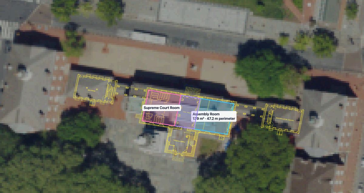
The same with lower-resolution imagery
Sources
Drawings: Historic American Buildings Survey, Lincoln Memorial (HABS DC-3, sheet 8) and Independence Hall (HABS PA-1430, sheet 3), Library of Congress / National Park Service, public domain. Imagery: Orthophoto 2023 © District of Columbia, Open Data DC (CC BY 4.0); USDA NAIP via USGS The National Map (public domain).